
 Charles-Olivier Amyot
1 min read

One of the biggest challenges of a 3D optical displacement measurement test is often to keep the same area of a part in the field of view. Say hello to a single software interface to scan complex geometries as a point cloud or a full mesh and animate all your components in Six Degrees of Freedom (6-DoF).
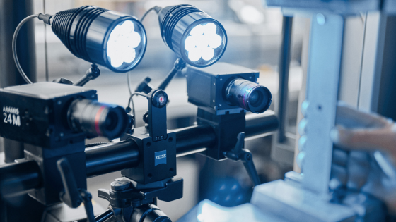
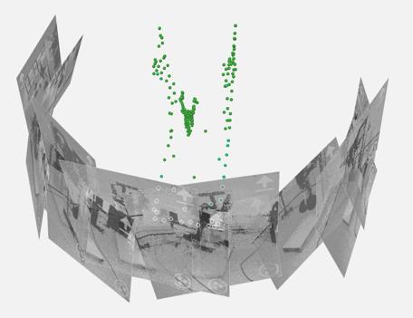
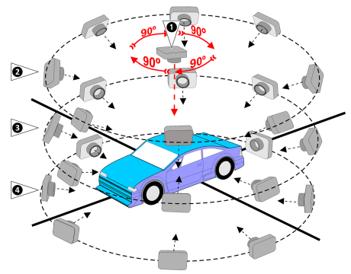
Thanks to the GOM Suite and any of the GOM hardware solutions, such as the ARAMIS Optical Motion, TRITOP Photogrammetry, or the GOM Scan 1, every image acquired is automatically aligned into a 3D coordinate system using our photogrammetry algorithms. Below is an example of 12 positions acquired by an ARAMIS system in an umbrella around an airplane landing gear to generate a point cloud from the sides and front.
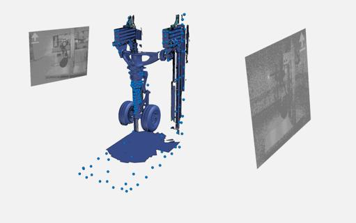
These reference points were then used to align two ARAMIS systems in a single project and a shared global coordinate system throughout the recording of the landing gear deployment test. Shown below are the combined measurements from two systems precisely aligned with photogrammetry on either side of the gear.
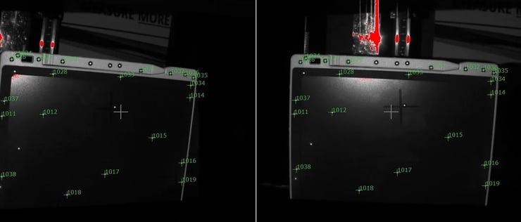
The GOM Suite can use coded markers or simple circular sticker dots. Regardless, the software will identify the center point by best-fitting an ellipse from the image contrast data and will assign a unique ID to each marker as the scan is being built one image (or pair of images when using a stereo-sensor like the GOM Scan 1) at a time. Below are some uncoded markers already scanned and identified overlaid on a live image view during a point cloud scan of a tablet.
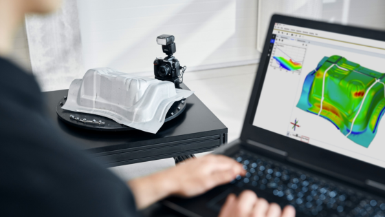
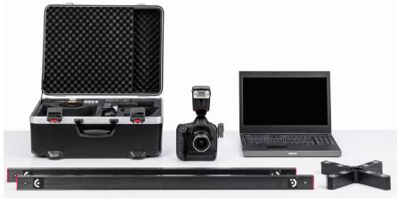
A point cloud can also be generated with a single-camera sensor, like the TRITOP Photogrammetry system. This handheld DSLR camera solution offers more flexibility to image around larger structures with a much higher pixel resolution, therefore maintaining extremely high precision. Below is a TRITOP camera with medium-sized carbon-fiber calibration artifacts which are used to provide measurement traceability and real accuracy.
To compensate for the lack of a stereo-calibration to orient the data, coded targets (shown above on small reference crosses with 8 coded markers each) can be spread around the measurement area. These coded markers provide triangulation data to compute a bundle adjustment of the image series. A complete 360° scan can be achieved by taking images in a similar fashion as pictured below.
These various techniques are all viable solutions to create a point cloud that can then be animated in 3D space in relationship to other components. For example, the more complex and complete geometry of the tablet shown previously allows for the creation of a local coordinate system defined along the edges of the device on the back face corner. Measurements of angular rotation/velocities and X-Y-Z displacement/accelerations can all be measured at that specific location in Six Degrees of Freedom (6-DoF). Moreover, as the device is doing a full rotation around its corner, the ARAMIS Optical Motion data can identify either side of the point cloud to continue tracking the tablet coordinate system (Device CS) as shown in the video below.
Conclusion
If you need to measure 3D displacement, there is only one software platform that can provide a complete workflow in a single software environment that supports a variety of algorithms to seamlessly scan complex geometries as a point cloud or a full mesh and animate all your components in Six Degrees of Freedom (6-DoF). That software is the GOM Suite and there is simply none other that can do this.
to infinity and BEYOND...
Using the small and compact GOM Scan 1, you can also build a point cloud and identify it in an ARAMIS High-Speed project. This is the only way to properly define the local coordinate system of a device and track it as it bounces and changes position. A quick scan could save you a lot of time and money in setup and botched drop tests. Talk with one of our Technical Account Managers to find out more.

1 min read
Battery Measurements with Digital Image Correlation
In the battery industry, precise measurement is critical for ensuring high-quality products that meet strict specifications. Traditional measurement...
1 min read
WEBINAR: Zeiss Inspect Software Launch
If you missed our Webinar: ZEISS INSPECT SOFTWARE LAUNCH, we have you covered. Just click the button below, fill out the attached form, and follow...